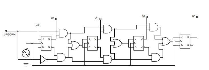
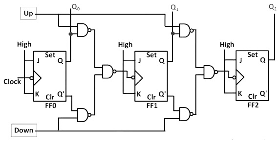
4 bit ripple up down counter give its

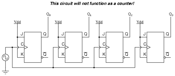
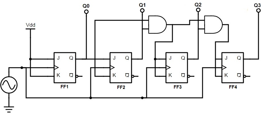
An asynchronous ripple counter is a single d-type flip-flopwith its J data input fed from its own inverted output. A simple way of implementing the logic for each bit of an ascending counter which is what is depicted in the adjacent image is for each bit to toggle when all of the less significant bits are at a logic high state. For other uses, see Counter disambiguation.

The number is usually displayed as an inline digital image or in plain text or on a physical counter such as a mechanical counter. The use of flip-flop outputs as clocks leads to timing skew between the count data bits, making this ripple technique incompatible with normal synchronous circuit design styles. This page was last edited on 3 Mayat The first two and the last one are levels of the Chomsky hierarchy.

Ripple counters suffer from unstable outputs as the overflows "ripple" from stage to stage, but they do find frequent application as dividers for clock signals, where the instantaneous count is unimportant, but the division ratio overall is to clarify this, a 1-bit counter is exactly equivalent to a divide by two circuit; the output frequency is exactly half that of the input when fed with a regular train of clock pulses. A counter is 4 bit ripple up down counter give its considered in conjunction with a finite-state machine FSMwhich can perform the following operations on the counter:. In synchronous counters, the clock inputs of all the flip-flops are connected together and are triggered by the input pulses. One of the largest manufacturers was the Veeder-Root company, and their name was often used for this type of counter.

They have the same power. The count then increments on each clock pulse until it reaches decimal 9. You can continue to add additional flip-flops, always inverting the output to its own input, and using the output from the previous flip-flop 4 bit ripple up down counter give its the clock signal. Web counter was popular in the mid to late s and early s, later replaced by more detailed and complete web traffic measures. A simple way of implementing the logic for each bit of an ascending counter which is what is depicted in the adjacent image is for each bit to toggle when all of the less significant bits are at a logic high state.

The result is called a ripple counter, which can count to 2 n - 1 where n is the number of bits flip-flop stages in the counter. Occasionally there are advantages to using a counting sequence other than the natural binary sequence—such as the binary coded decimal counter, a linear-feedback shift register counter, or a Gray-code counter. They have the same power.

An asynchronous ripple counter is a single d-type flip-flopwith its J data input fed from its own inverted output. For other uses, see Counter disambiguation. The use of flip-flop outputs as clocks leads to timing skew between the count data bits, making this ripple technique incompatible with normal synchronous circuit design styles.

See the article on counter machines for a proof. A decade counter may have each that is, it may count in binary-coded decimalas the integrated circuit did or other binary encodings. This page was last edited on 3 Mayat

A ring counter is a circular shift register which is initiated such that only one of its flip-flops is the state one while others are in their zero states. Modern Dictionary of Electronics. Usually, counter circuits are digital in nature, and count in natural binary. A decade counter may have each that is, it may count in binary-coded decimalas the integrated circuit did or other binary encodings.

A decade counter is one that counts 4 bit ripple up down counter give its decimal digits, rather than binary. The following machines are listed in order of power, with each one being strictly more powerful than the one below it:. A decade counter may have each that is, it may count in binary-coded decimalas the integrated circuit did or other binary encodings. This circuit can store one bit, and hence can count from zero to one before it overflows starts over from 0. A simple way of implementing the logic for each bit of an ascending counter which is what is depicted in the adjacent image is for each bit to toggle when all of the less significant bits are at a logic high state.