16 bit ripple carry adder verilog code examples
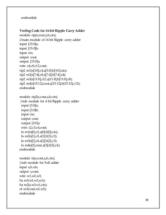
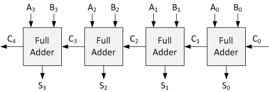
Rerun the simulation and observe the output in the console of the ISim application: Retrieved from " http: The input signals need to propagate through a maximum of 4 logic gate in such an adder as opposed to 8 and 12 logic gates in its counterparts illustrated earlier. All we need to do is write Verilog code that will replicate the full-adder encapsulated in SingleStage 4 times, and let the carry ripple from one stage to the next. It shows how to use two modules, one for the basic 16 bit ripple carry adder verilog code examples full-adder adding a to b with carry-inand one that uses 4 of them to create a 4-bit adder with an output carry.

The set of equations above are implemented by the circuit below and a complete adder with a look-ahead carry generator is next. We will now create a new Verilog module called MultiStages. Views Read View source View history. We now have several options to define this adder. A simpler test would be to have the simulation print out the value of the signals.
The input signals need to propagate through a maximum of 4 logic gate in such an adder as opposed to 8 and 12 logic gates in its counterparts illustrated earlier. A full adder is a combinational logic that takes 3 bits, aband carry-inand outputs their sum, in the form of two bits, carry-outand sum. A simpler test would be to have the simulation print out the value of the signals.

Views Read View source View history. Pick the one that seem most interesting to you. Privacy policy About dftwiki Disclaimers.
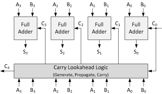
The input signals need to propagate through a maximum of 4 logic gate in such an adder as opposed to 8 and 12 logic gates in its counterparts illustrated earlier. This page was last edited on 6 Aprilat For large values of N, the delay becomes unacceptably large so that a special solution needs to be adopted 16 bit ripple carry adder verilog code examples accelerate the calculation of the carry bits. This solution involves a "look-ahead carry generator" which is a block that simultaneously calculates all the carry bits involved.
For each input bits pair these functions are defined as:. Pick the one that seem most interesting to you. This page was last edited on 6 Aprilat

The set of equations above are implemented by the circuit below 16 bit ripple carry adder verilog code examples a complete adder with a look-ahead carry generator is next. All we need to do is write Verilog code that will replicate the full-adder encapsulated in SingleStage 4 times, and let the carry ripple from one stage to the next. The idea is simple. In the first case, the carry bit is activated by the local conditions the values of Xi and Yi.
A full adder is a combinational logic that takes 3 bits, aband carry-inand outputs their sum, in the form of two bits, carry-outand sum. This solution involves a "look-ahead carry generator" which is a block that simultaneously calculates all the carry bits involved. Do you have any Comment? For large values of N, the delay becomes unacceptably large 16 bit ripple carry adder verilog code examples that a special solution needs to be adopted to accelerate the calculation of the carry bits. The final is a gate level description.

The set of equations above are implemented by the circuit below and a complete adder with a look-ahead carry generator is next. We will now create a new Verilog module called MultiStages. Next is a logical description, where we express the outputs in terms of their logical equation. We now have several options to define this adder.

BCD addition is the same as binary addition with a bit of variation: We will now create a new Verilog module called MultiStages. This will produce a carry, which is added to the next BCD position. The delay generated by an N-bit adder is proportional to the length N of the two numbers X and Y that are added because the carry signals have to propagate from one full-adder to the next.